Here's some pics along the way. The first pic is all of the parts being used. This is the roller kit from Opentracker Racing Products. It replaces the stock rubber bushings with roller bearings, which in theory will allow the suspension to work easier without binding, and feel more solid. I'll know in a few weeks if that is true, but for now it seemed like a worthwhile and fun project to do. You can see that the UCA has already been modified to accept the bearings. I ordered new UCAs from John at Opentracker since I really messed mine up when I tried to do the modifications myself without the right tools. Look for previous posts in this blog to see the gory details. (Lessons learned - don't rush, take your time, get the right tools for the job, ask for help when you need it, and don't be afraid to try something new!)

I blasted the paint off of the UCA's interface before welding. I looked around for a decent blast cabinet and finally settled on the one below. It operates off of relatively low volume, is big enough for what I need to do, can be stashed into a corner when not in use, and was priced right at $99 from Tractor Supply Company. I'm using 80 grit glass beads, which seem to do exactly what I need for now without cutting too much or overheating.

The first step was to get the parts layed out and tack welded in place. I spent quite some time doing this, hopefully it was worth it. When I shaft with the bearings and sleeves in the UCA I found the fit looser than expected, about a 1/16" of freeplay. Since I could not figure out how to hold the sleeves exactly in the center of the UCA hole, I elected to use gravity to hold the sleeves at the back edge of the UCA, or towards the middle of the car when installed. To do this I set the UCA close to vertical using a wood block and let the shaft with the sleeves rest on the back edge. I used a set of digital calipers to center the sleeves, measuring from the outer edge of the sleeves to the UCA wall. Once I got the side to side error within a few thousandths of an inch I placed a couple of tack welds on each side.


Once tacked in place, I welded the sleeve around as much of the circumference as I could reach on both sides of the UCA wall. There are some areas I could not get my welder into, but luckily the tight areas on one side were open on the other, so between the two sides I did manage to weld the entire circumference. I am using my Hobart Handler 140 MIG welder, set at 2 of 5, wire feed at 30, using 0.030" wire. My initial thought was to use a setting of 3 of 5, but I was fearful of burning through the sleeves so I used 2. Someone with more welding experience can tell me if I used the right setting. The welds are not pretty, but they look functional to me. If not, what's the worst that can happen? It's not like a wheel could fall off the car. Oh yeah, I guess a wheel could fall off the car if these welds fail...
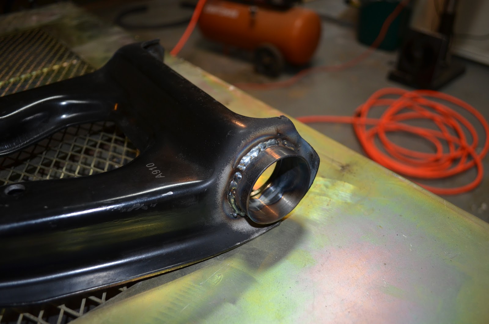

Welding warped the sleeves a bit, as expected, to the point that the bearings would not slide in anymore. I used a cylinder hone and a Dremel with a sanding drum to round them out again so that the bearings would go in. The basic process was to use the hone to open the sleeves enough to force the bearings in by lightly hammering on them with a brass punch, then use the punch to drift them back out. This would leave marks on the inside of the sleeve where the bearing was rubbing, which I would then attack with the Dremel and sanding drum. After the Dremel, a few more cuts with the hone to clean it up then repeat the whole process again. After a few iterations the sleeves were round enough to press the bearings in place mostly by hand, with a few gentle taps with the hammer and brass punch.
Once everything was fitting together again, the UCA went back into the blast cabinet to clean up the welds before painting. After blasting and washing with mild soap and water, they looked like this.

I used rolled up stiff construction paper to mask off the inside of the sleeves and painted with standard gloss black Rustoleum. I do not know what color I eventually want the suspension components to be, so for now the black is good enough. Once I tear down the entire car for painting I'll spray good paint on all of the suspension components.

So, finally here are photos of the finished and assembled upper control arms. I have not painted the shafts yet, I'll get those when I do the touch-up paint needed to cover the scratches and marks from assembly. I am happy with the results, the rollers make a huge difference in freedom of motion.


I put the roller spring perches I did awhile back in place. I had to laugh as I was taking this pics as the roller perches kept wanting to go nose up as in the second picture on their own accord. Again, freedom of motion in this set up is much much better than with the stock rubber bushings. I'm looking forward to getting all this back into the car and doing a test drive.


My only concern with this setup is my welding skills, or lack thereof. The welds on the UCAs are ugly, but I think effective. However, looking at my first welds done on the spring perches has me worried since they look real bad to me now. I suspect I will be redoing them before I am done. But, that is not a bad thing. I am taking on this project for the fun of it, and for learning new things including welding. I had to start somewhere, and if I need to redo some bits thats ok. It's more opportunity to have more fun and learn something in the process.
Next up - roller bearings and removable ball joints in the lower control arms.
Happy building! Please leave any comments or questions.
No comments:
Post a Comment