Total Pageviews

Sunday, January 29, 2012

Start of reassembly

I am done with fabrication of front suspension parts, I think.  It's time to start putting parts back on the car.  Woohoo!

Starting on the driver side, I cleaned up all of the road gunk using a scraper and wire brush on my electric drill.  It's not a perfect clean up job, but good enough to start reassembly.  The full cleanup will come later after I completely disassemble the car.  Good enough is good enough for now.

When I got through all of the gunk on the lower control arm pivot point, I discovered that the old bushing had started to work a hole into the mount.  This part will need to be replaced later, but I think it will hold for now.  You can see the wear marks in this pic on the left inside of the channel.
The rest of the structure on this side seems sound.  I have not started on the other side yet, but I suspect I will find similar damage.

I stopped work when the wife had my birthday dinner on the table, but before then I was able to reinstall the fuel line and brake line that runs through the driver side fender well.  I also cleaned up the wheel hub and bearings.  No pics of these parts since they are kinda boring.

I got to thinking during dinner that with this fuel line reinstalled, there's no reason why i can't fire up the engine.  This week I will change the oil, get some fresh fuel, charge the battery, and she if the old gal still has some life in her.

More to follow!

Fixing cracks

Along with the upper and lower control arm fabrication, I did lots of little jobs to prepare for installation of the new suspension.  These jobs are mostly cleaning, blasting, and painting an assortment of bits that need to be reinstalled.

Amongst these bits is a fairly large fabricated plate that sits high in the fender wells and boxes in the structure around the front coil springs.  I have no idea what the proper name for this plate is.

The plate on the driver side was straight forward - scrape off the accumulated road gunk, degrease, sand blast, and paint.  No problem.  The plate on the passenger side started the same, until it came out of the sand blast cabinet.  Upon inspection I found six cracks and a broken spot weld. 

Here's a pic.  I marked all of the cracks I found with a red Sharpie.

 Here's a close up of the broken spot weld.  You can see that the brace has lifted off of the plate.
Upon closer inspection, I discovered that the spot weld on this brace did not break.  In reality, when Ford put this together almost 40 years ago, they missed the spot weld.  The spot weld is there, just not on the brace but about a quarter inch to the side.  American quality control in the 70's!  Therefore this brace was never welded.  I suspect this is what caused all the cracks.  Without the stiffness the brace adds to the plate, I suspect that the plate flexed too much which allowed the cracks to form.  So I hope that welding the brace and welding the cracks will fix the problem.

I stop drilled all of the cracks, then welded along the cracks and closed the stop drill holes.  I don't know if I really needed to drill the stop holes or not, but I did it anyway.  Made me feel better if nothing else.

Here is the plate after welding.  I used my Hobart Handler setting it on 2 of 5 and wire speed of 25.  It seemed to burn through in most places, but I had to reweld from the other side in a couple of spots.

After welding I ground down the welds, and used my bench mounted wire wheel for general clean up.  Here's a pic after grinding.

 Here's the panel after painting.
I think it turned out fairly well.  If you look you can see where I did not do a perfect job with the grinding, but since this panel is well hidden up in the wheel well I won't worry about it.  Besides, I am not doing a concourse restoration, so no one will really care.

Wow, my parts count is finally going down!

Yay!  I started reassembly today!

But before I go into those details, I promised awhile back to post about the fabrication on the lower control arms, so here goes.

Like the upper arms, I am using the roller kit from Opentracker Racing with the removable lower ball joint, spherical bearing in the pivot, and reinforcement that boxes the arm, making it very strong and stiff.  I probably don't really need the reinforcement, but I thought it would be a fun project.

The first step is cleaning up the original arm, popping out the stock rubber bushing, and drilling out the riveted-in stock lower ball joint.  Taking out the bushing was easy.  They were so worn on both sides that they just fell out.  So the first real work was taking out the lower ball joint.

The first step was drilling a 1/8th hole through the rivet, then slowly enlarging it.  I had originally intended to keep drilling until the rivet was essentially gone, but I read in my favorite Mustang forum that once drilled you can use a die grinder to cut a slot in the rivet head, then use a cold chisel to easily pop the head off.  Then an easy matter to pound the remainder of the rivet out.  So that's what I did.

Here's a pic of the arm with the original 1/8th inch hole drilled through all three rivets.
Next pic shows the holes just a bit larger.
 I don't have pics of cutting the slots across the rivet heads or pounding the rivets out, but it went real easy at that point.  Once the rivets are out the ball joint basically falls out.  What's left is a dome that the ball joint rode in.  This dome is one piece of hardened steel that is spot welded onto the bottom of the arm.  Here's a pic of the dome from the top.  At this time I did not take a pic from the bottom.
 The objective with the removable ball joint is to weld a sleeve that has internal threads to the hole where the original ball joint was, then simply screw in the new ball joint.  I thought "No problem", jigged up the arm in my drill press with a 2 inch bi-metal hole saw, set the RPM to 350, squirted on a bit of cutting oil, and promptly flattened the teeth on my hole saw.  Damn, that hardened steel is tough!  One ruined hole saw now in the scrap pile.

So then I thought "ok, I'll use a small drill to drill a series of holes around the perimeter, then cut out along the holes."  One dull and dead drill bit later, with nary a scratch on the steel, I abandoned that plan too.

I considered drilling out the spot welds that hold this hardened steel on the lower arm, but was uncomfortable doing so since the arm itself is not all that thick, and I suspected that I would want the structure that the hardened steel provides.  My quest now turned into finding something I could cut this crap with.  That something ended up being a die grinder.  I bought a 2 inch air driven grinder from Northern Tool along with a bag of a dozen cut off wheels.  With these wheels I was able to cut off the dome, and cut a series of radial slots in the remaining steel, as you can see in this pic.

I then used a small 1 inch cutting wheel and a 1 inch grinder wheel in my Dremel to cut out the rest.  Once I figured out how to do this, and got into the rhythm of it, I was able to cut out the hole in about an hour.  Once rough cut, I used a grinding stone to round out the hole to the size needed to insert the sleeve for the new removable ball joint.  Here's a pic of the arm from below with the hole at proper size.  You can see the hardened steel plate spot welded to the underside.
 Same arm from above.
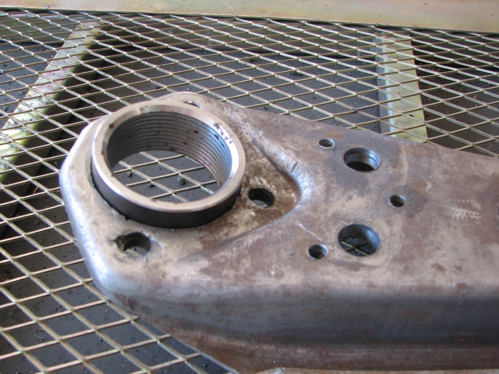
 Here's a pic with the sleeve pressed into place for a test fit.  You can see the internal threads for the new ball joint.
And here's a pic of the sleeve for the spherical joint that replaces the stock rubber bushing, pressed into place for trial fit.
After the test fitting, it was into the sand blast cabinet for clean up before welding.  Here's a pic of the modified arm next to the other lower control arm still in it's original state as it came off the car.  It shows the amount of work that went into the fabrication to this point!
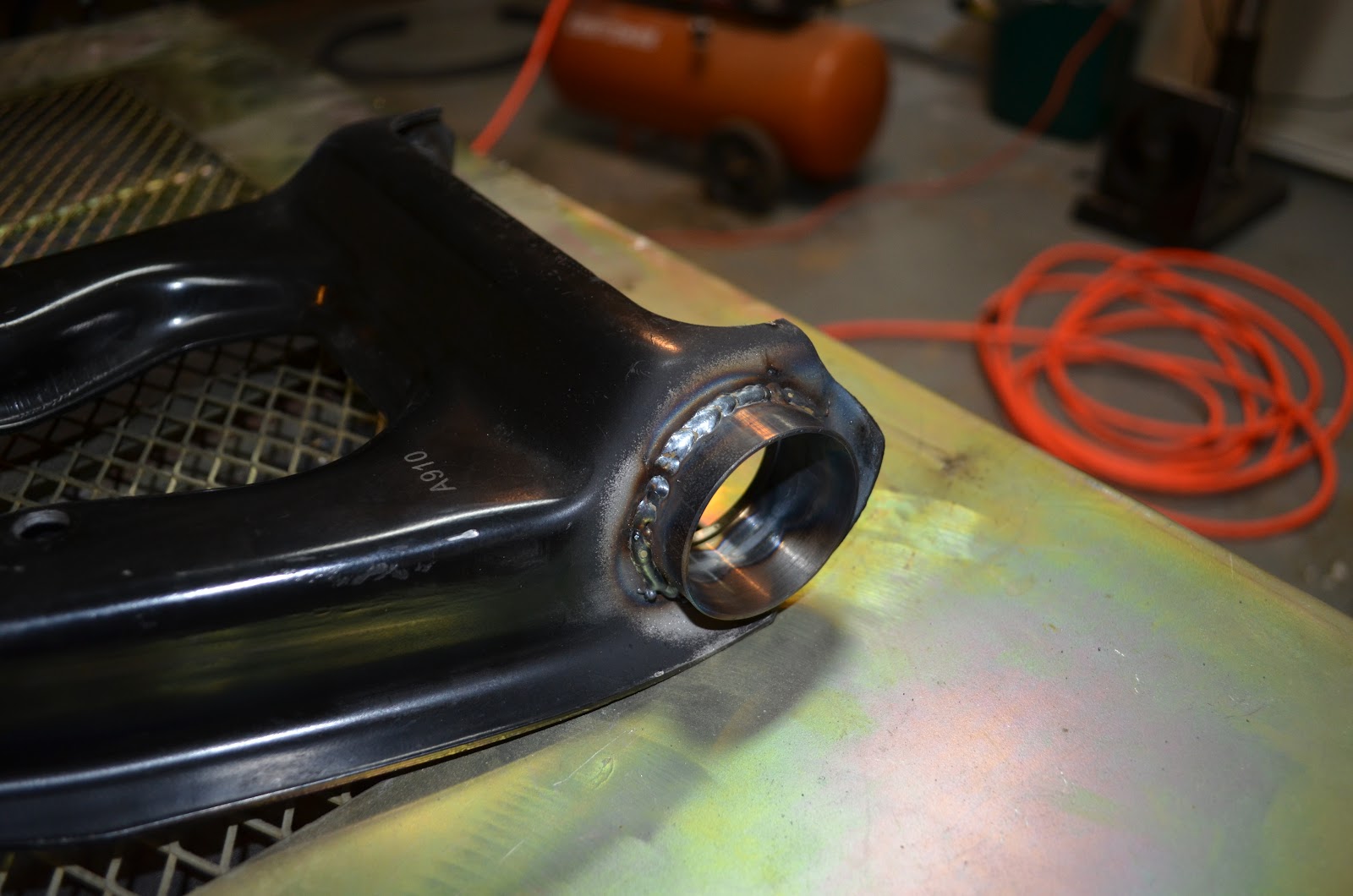
I took my time in welding in the two sleeves.  John at Opentracker cautioned me to weld about a quarter of the perimeter at a time, letting it cool completely in between welding, to prevent the sleeve from shrinking.  I took his word for it and took some time to do the welding.  For the ball joint sleeve I had my Hobart Handler 140 on 3 of 5, with wire speed of about 30.  For the spherical joint sleeve, I turned it down to 2 of 5 and wire speed of about 25, since the arm is a bit thinner there.  I welded both sides of the sleeves.  Here's a pic of the underside of the ball joint sleeve after welding.
After the sleeves are welded, and I tested the fit of the ball joint and spherical bearing, I started on the reinforcement of the arm.  The reinforcement consists of a simple plate that is welded to between the side walls on the underside of the arm and to the sleeve for the lower ball joint.  This ties everything together and makes for a very strong and stiff assembly.  This plate has holes in it already for the lower ball joint and access to the sway bar link, but I had to cut the holes to get access to the bolts for the strut rod.  The plate does not come with these holes since the stock strut rods attach to the arm through pressed in studs, but I am using adjustable strut rods from Global West which use larger bolts instead of the studs.

I clamped the reinforcement plate in place, then ran a pencil around the wholes for the strut rod bolts to mark where I needed to drill.  Here's the plate with the marks.
Back to the drill press, this time with a a 1 1/8th inch whole saw, which allowed clearance for the nuts, and I have a reinforcement plate just about ready to install.  Right?
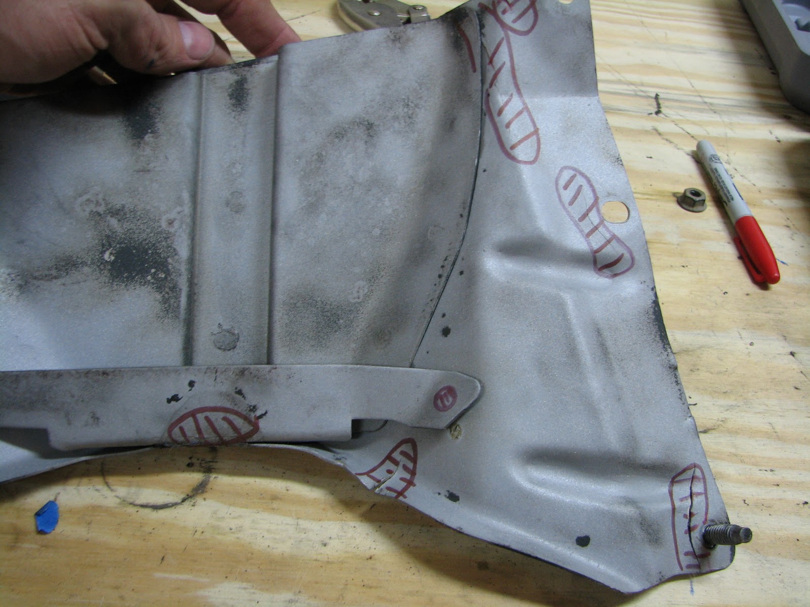
Wrong!  The holes I just cut are big enough for the nuts, but not big enough to get a socket over the nuts to tighten them.  Almost a big mistake there!  Here's a pic of the plate, clamped in place, with the bolts and nuts for the strut rods.  The marks on the plate are where I need to enlarge the holes to get a socket onto the nuts.
Luckily this was fairly easy to do.  I used a medium sized stone in my Dremel and enlarged the holes until I could get a socket on the nuts with a bit of clearance.  By the way, you might wonder why the arm is already painted blue in the pic above.  I painted the lower side of the arm, and the inside of the reinforcement plate, before welding it all together since I new I would not be able to paint the inside once assembled.  Although the design does allow water to escape, I still wanted to have as much protection as possible.  I know that the welding process will burn off the paint around the joints, but at least most of the inside of the arm will have some protection.

Now that the reinforcement plate is done, it's time to weld.  I held the plate in place using C-clamps and vise grips, as shown below.  I set my welder on 2 of 5 and wire speed 25 again, since the reinforcement plate is thinner than the arm.
After welding, I sand blasted the whole assembly again using 80 grit glass beads, and painted the arm Ford blue.  I just wanted something other than the standard black.  Here's the completed and assembled arm.
 And the view from the bottom with the reinforcement plate welded in.
Overall a relatively easy and fun project to do.  The hardest part was figuring out how to cut the hardened steel, but even that went quick once I figured it out.  This arm took me three days of work, the other arm took me about five hours.  I highly encourage you to try this project, if I can figure it out than anyone can.

Contact me if you have any questions or comments.  I would love to hear from my readers!

Saturday, January 21, 2012

Great progress on lower arms

I have made great progress, despite being down with a flu bug for almost a week and my work life dominating all of my time and weekends.  I have one lower arm complete, and got a good start on the second arm today.  I also took apart and refinished the tie rods on one side.  However, it is late, I am tired, and I want to go to my daughter's hockey game in seven hours, so I am not going to make a full post with pictures tonight.  I'll try and do that tomorrow.  But for now, here is a pic of the completed lower control arm.

On another note, I have been adding to this blog for a year or two now, and have had few hundred visits.  If you are reading this, please click on the join button to the right.  I won't send any spam or give your name to anyone, I would just like to know who is reading.

Happy building, and please leave any comments or suggestions!

Tuesday, January 10, 2012

Another week

I did not expect these lower control arms to be so difficult.  After returning from a trip to Detroit that took almost all week last week, I have almost completed the removal of the lower ball joint from on control arm.  That hardened steel is damn tough!  Pictures and more to follow, but for tonight I am tired.  Gonna watch the Stars beat the Ducks, then off to bed.

Monday, January 2, 2012

Now the lower control arms

I started on the lower control arms today.  These are proving to be much more challenging than the uppers.  There are more parts to them, and more mods to be made to the stock arms.  I'll post the real details later, but for now I'll just say that drilling and cutting through hardened steel is much tougher than I thought it would be.  I bent one drill bit in the process already and I don't even have the first arm disassembled yet.  So off to Northern Tool tomorrow to pick up a smaller grinding tool and some bigger stones.

Then to top it off, my parts washer pump decided to quit working.  I got it to run intermittently, but I think I need a new pump already.  I suppose that's the price I pay for buying the lowest cost stuff instead of the best value stuff.  You'd think that I would have learned that lesson well a long time ago...

With all that being said, I still think it was a good day of progress on the Mustang.  I'm still having fun with it, and would much rather stay home tomorrow and keep working on it instead of going back to work.

More to follow.

Sunday, January 1, 2012

As promised, some words about Upper Control Arms.

So I finally got my upper control arms done.  In all honesty I was a bit hesitant to build them since I am not real confident in my welding yet.  I spent most of the day last Wednesday finishing the welding on my deck railing.  Those did not turn out too bad, so I screwed up my courage, laid out the parts, and got to work.

Here's some pics along the way.  The first pic is all of the parts being used.  This is the roller kit from Opentracker Racing Products.  It replaces the stock rubber bushings with roller bearings, which in theory will allow the suspension to work easier without binding, and feel more solid.  I'll know in a few weeks if that is true, but for now it seemed like a worthwhile and fun project to do.  You can see that the UCA has already been modified to accept the bearings.  I ordered new UCAs from John at Opentracker since I really messed mine up when I tried to do the modifications myself without the right tools.  Look for previous posts in this blog to see the gory details.  (Lessons learned - don't rush, take your time, get the right tools for the job, ask for help when you need it, and don't be afraid to try something new!)


I blasted the paint off of the UCA's interface before welding.  I looked around for a decent blast cabinet and finally settled on the one below.  It operates off of relatively low volume, is big enough for what I need to do, can be stashed into a corner when not in use, and was priced right at $99 from Tractor Supply Company.  I'm using 80 grit glass beads, which seem to do exactly what I need for now without cutting too much or overheating.


The first step was to get the parts layed out and tack welded in place.  I spent quite some time doing this, hopefully it was worth it.  When I shaft with the bearings and sleeves in the UCA I found the fit looser than expected, about a 1/16" of freeplay.  Since I could not figure out how to hold the sleeves exactly in the center of the UCA hole, I elected to use gravity to hold the sleeves at the back edge of the UCA, or towards the middle of the car when installed.  To do this I set the UCA close to vertical using a wood block and let the shaft with the sleeves rest on the back edge.  I used a set of digital calipers to center the sleeves, measuring from the outer edge of the sleeves to the UCA wall.  Once I got the side to side error within a few thousandths of an inch I placed a couple of tack welds on each side.


Once tacked in place, I welded the sleeve around as much of the circumference as I could reach on both sides of the UCA wall.  There are some areas I could not get my welder into, but luckily the tight areas on one side were open on the other, so between the two sides I did manage to weld the entire circumference.  I am using my Hobart Handler 140 MIG welder, set at 2 of 5, wire feed at 30, using 0.030" wire.  My initial thought was to use a setting of 3 of 5, but I was fearful of burning through the sleeves so I used 2.  Someone with more welding experience can tell me if I used the right setting.  The welds are not pretty, but they look functional to me.  If not, what's the worst that can happen?  It's not like a wheel could fall off the car.  Oh yeah, I guess a wheel could fall off the car if these welds fail...


Welding warped the sleeves a bit, as expected, to the point that the bearings would not slide in anymore.  I used a cylinder hone and a Dremel with a sanding drum to round them out again so that the bearings would go in.  The basic process was to use the hone to open the sleeves enough to force the bearings in by lightly hammering on them with a brass punch, then use the punch to drift them back out.  This would leave marks on the inside of the sleeve where the bearing was rubbing, which I would then attack with the Dremel and sanding drum.  After the Dremel, a few more cuts with the hone to clean it up then repeat the whole process again.  After a few iterations the sleeves were round enough to press the bearings in place mostly by hand, with a few gentle taps with the hammer and brass punch. 

Once everything was fitting together again, the UCA went back into the blast cabinet to clean up the welds before painting.  After blasting and washing with mild soap and water, they looked like this.

I used rolled up stiff construction paper to mask off the inside of the sleeves and painted with standard gloss black Rustoleum.  I do not know what color I eventually want the suspension components to be, so for now the black is good enough.  Once I tear down the entire car for painting I'll spray good paint on all of the suspension components.

So, finally here are photos of the finished and assembled upper control arms.  I have not painted the shafts yet, I'll get those when I do the touch-up paint needed to cover the scratches and marks from assembly.  I am happy with the results, the rollers make a huge difference in freedom of motion.

I put the roller spring perches I did awhile back in place.  I had to laugh as I was taking this pics as the roller perches kept wanting to go nose up as in the second picture on their own accord.  Again, freedom of motion in this set up is much much better than with the stock rubber bushings.  I'm looking forward to getting all this back into the car and doing a test drive.


My only concern with this setup is my welding skills, or lack thereof.  The welds on the UCAs are ugly, but I think effective.  However, looking at my first welds done on the spring perches has me worried since they look real bad to me now.  I suspect I will be redoing them before I am done.  But, that is not a bad thing.  I am taking on this project for the fun of it, and for learning new things including welding.  I had to start somewhere, and if I need to redo some bits thats ok.  It's more opportunity to have more fun and learn something in the process.

Next up - roller bearings and removable ball joints in the lower control arms.

Happy building!  Please leave any comments or questions.